
INVESTIGATIONS OF VEGETABLES COLD STORE WITH INDIRECT COOLING SYSTEM OF THE VARIABLE CAPACITY
Grzegorz MIZERA1,
Dariusz BUTRYMOWICZ2, Jerzy GAGAN2, Kamil ŚMIERCIERW2,
Andrzej SZCZEŚNIAK3
1Institute of Fluid-Flow Machinery of Polish Academy of Sciences, ul. Fiszera 14,Gdansk,80-231, Poland
2Bialystok University of Technology, ul. Wiejska 42A, Bialystok,15-351, Poland
3REMSTAT, Dąbrowszczaków 11, 80-373 Gdansk, Poland
d.butrymowicz (at) pb.edu.pl
ABSTRACT
Direct and indirect cooling refrigeration systems of variable cooling capacity in application to the cold storage of the Chinese cabbage were analysed in the paper. This refrigeration unit has been designed to meet vegetables storage technical and technological requirements. Paper presents the technical assessment of the tested designs of the applied refrigeration units in terms of air and products temperatures during storage test. The differences in relative humidity in both chambers during test were also presented.
- INTRODUCTION
The fundamental condition for good storage of most vegetables is to keep them in a steady state temperature which should be as close as possible to cryoscopic temperature (but not lower since it would cause freezing). According to van’t Hoff law, lowering of vegetables temperature slows down the life activity of stored vegetables including breathing. Another important factor having impact on quality of vegetables is humidity of air. Only a few percent of vegetable mass is called dry matter and the rest is water. This is the reason why most of vegetables lose very easily moisture if they are kept in too dry air, Adamicki and Czerko (2002), Mizera et al. (2010).
Next factor having impact on quality of stored vegetables is water condensation on vegetables. The dropping of the condensate is the cause of vegetables decay and mould growth. Capacity of refrigeration unit should ensure the appropriate cooling rate of harvested vegetables. Quick cooling reduces the intensity of vegetables breathing and prevents the rapid development and spread of pathogens, Mazza (1989), Gross et al. (2002). The another important factor for contemporary refrigeration units for vegetables storage is high energy efficiency and environmental protection.
The discussed systems are appropriate for vegetables cold storage chambers of small and medium capacity. The results of the experimental investigations of cold storage of Chinese cabbage in three storage-chambers at the Research Institute of Horticulture, Skierniewice, Poland, were presented. Two of the chambers were equipped with refrigeration systems of innovative types while the third one was classic direct evaporation system. The aim of the paper is the technical assessment of all of the refrigeration systems in terms of the desired temperature and relative humidity of air inside the cold storage chambers as well as temperature of the stored product, i.e. Chinese cabbage. Technological and operational advantages of the proposed solutions of the system design can be applied to various vegetables and different storage-periods.
- TEST STORAGE CHAMBERS STATION
Three existing storage chambers located on the premises of the Institute of Horticulture Department of Stored Vegetables in Skierniewice, Poland, were adapted to the research test. Figure 1 shows a plan of the location of storage chambers (assigned as Chamber No. 1, 2, and 3), a compression unit (assigned as A1, A2, and A3) and the power supply-control & measuring electric board.
The same lamella, fan air coolers were installed in all of the tested cold storage chambers. The air coolers were made by PPUCH Tarczyn (the series type: G01G35Cu25Al040051050WCVP0112, type 12). Each of the air coolers had the heat transfer surface 3 m2 consisted of the aluminium lamellas and copper tubes of 10 mm diameter. The fins spacing was 6 mm. The each air cooler was equipped with three fans and electric heater to defrost, see Fig. 2. Each of the cold storage chamber worked with refrigeration condensing unit (all of the same type of UNE 9213 GK, Embraco–Aspera) equipped with a lamella fan air cooled condenser, see Fig. 3. The systems were operated with refrigerant R507.
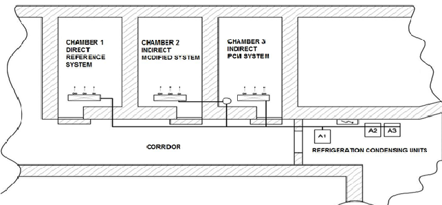 Fig. 1. Scheme of the test storage chambers.
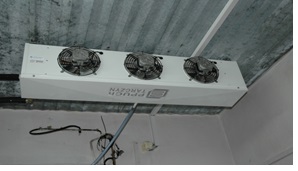 Fig. 2. View of the fan-air cooler applied in tests.
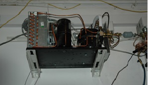
Fig. 3. Condensing refrigeration unit applied in tests.
The same kind of the air coolers and the refrigeration condensing units simplify the evaluation of operation of each of refrigeration system in the tested cold storage chambers.
- TESTED REFRIGERATION SYSTEMS
The first discussed cooling system that was applied in the cold storage Chamber No. 1 was treated as the reference system. Traditional direct cooling expansion system equipped with thermostatic expansion valve was applied. The schematic of this system is presented in Fig. 4. This system was controlled by means of the standard method. The compressor started when the temperature of the air at the inlet to the air cooler reached the set point. The compressor stopped the operation when temperature of air decreased below the neutral zone. The defrosting process of the air cooler started when the lamella temperature was lower than -2 °C for a period of two hours. It stopped when the temperature measuring sensor reached + 4 °C.
Fig. 4. Cooling system applied in Chamber No. 1; 1 – air cooler; 2- compressor; 3 – condenser; 4 – liquid vessel; 5 – moisture indicator; 6 – filter-drier; 7 – solenoid cut-off valve; 8 – thermostatic expansion valve.
In the tested cold storage chamber No. 2 the indirect refrigeration system was applied. Cooling system was upgraded in comparison with the system applied in Chamber No. 1. In order to control the capacity of the air cooler, additional indirect system with glycol as heat transfer fluid was applied. This system consisted of a plate glycol cooler (2), buffer tank (6), and a circulation pump (2). The glycol vessel was selected for this system on the basis of previous studies, Gościk et al. (2011), Kwidziński et al. (2011). The system capacity control is achieved by changing of the compressor operation time during 10-minute cycles. Duration of 10-minute cycles coincide with the recommended compressor manufacturers recommendations as to the time interval between two starts of the compressor.
By changing compressor operation time (within 10-minute cycle) the average temperature of the circulating glycol is also varying. Extension of the operating compressor time causes the decrease of glycol temperature. Reduction of the operating time of the compressor increases glycol temperature. This solution allows for continuous adjustment of the air cooler performance by changing the temperature difference between the circulated air in the chamber and cooled glycol. This approach for the control of the on/off compressor operation enables of the variable capacity performance of the air cooler. This simple technical solution is sometimes called as „cooling hybrid” as a combination of discrete and continuous control of the system capacity.
The schematic of the glycol circulation and R507 refrigeration unit is shown in Fig. 5. The refrigeration compressor operating time is adjusted by temperature of air leaving of the air cooler.
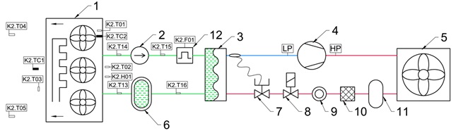
Fig. 5. Cooling system applied in Chamber No. 2;1 – air cooler; 2- circulating pump; 3 – glycol cooler;
4- compressor; 5 – condenser; 6 – glycol vessel; 7 – thermostatic expansion valve; 8 – solenoid cut-off valve; 9 – moisture indicator; 10 – filter-dryer; 11- liquid vessel; 12 – flow meter.
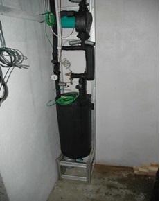
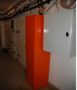
Fig. 6. Accessories for upgrading cooling system in Chamber No.1 to cooling system in Chamber No. 2:
the pre-prototype version (on the left); the prefabricated version (on the right).
Figure 6 shows a photograph of the additional equipment that is installed during the upgrading of the traditional refrigeration system with variable air cooler performance. The equipment consists of the glycol tank (6), glycol cooler (3) supplied with a thermostatic valve (7), and a circulation pump (6). The photograph of prefabricated version of upgraded construction is also presented in Fig. 6. The defrosting of the air cooler in the cooling system applied in the cold storage Chamber No. 2 is achieved by the electrical heater.
The cooling system that was applied in the cold storage Chamber No. 3 was more innovative. This system is presented in Fig. 7. In this solution the glycol tank (item 6 in Fig. 5) was substituted by a cold accumulator (item 13 in Fig. 7). The accumulator uses the phenomenon of phase change material (PCM) for the cold storage purpose. The accumulator is made of a plate heat exchanger. In this configuration glycol circulates through the first part of the heat exchanger while the second part of the heat exchanger is filled up with the PCM material. The temperature of PCM phase change was – 6 °C.
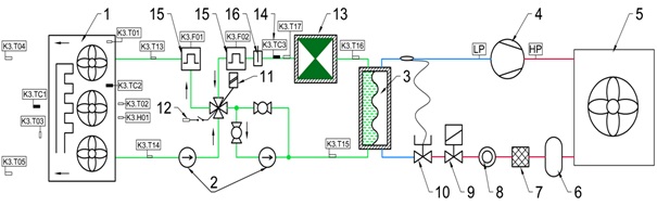
Fig. 7. Cooling system applied in Chamber No 3; 1- air cooler; 2 – circulation pumps;
3 – glycol cooler; 4- compressor; 5 – condenser; 6 – liquid vessel; 7 – filter-drier; 8 – moisture indicator;
9 – solenoid cut-off valve;10- thermostatic expansion valve; 11 – mixing valve; 12 – open switch;
13 – PCM accumulator; 14 – pressure sensor; 15 – mass flow meter; 16 – flow switch.
The special system presented in Fig. 7 was prepared to maintain air temperature in the air cooler outlet at the required level. This system consists of the two loops:
- the first loop (air cooler loop) includes the air cooler (1), the circulation pump (2), and the mixing valve (11);
- the second loop (accumulator loop) consists of the PCM accumulator (13), the mixing valve (11), the accumulator circulation pump (2), and the glycol cooler (3).
During compressor operation glycol temperature is reduced; when glycol temperature falls below -6 °C then PCM material starts to freeze and glycol temperature is almost constant. When glycol temperature starts to drop again that is the signal for the system that the freezing process of PCM has finished. The accumulator may be thought as loaded and compressor stops the operation. From this moment the PCM accumulator starts the unloading process. This process is finished when the mixing valve (item 11 in Fig. 7) is fully open and the controller receives signal “open switch” from the flow switch (item 12 in Fig. 7).
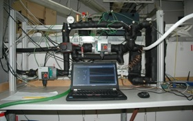
- b)
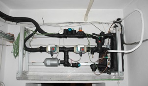
Fig. 8. Cooling system equipped with the PCM accumulator: a) during preliminary tests at the laboratory;
b) applied in the cold storage chamber at the Institute of Horticulture in Skierniewice.
A characteristic feature of this system is the usage of the PCM accumulator which let eliminate glycol tank. This significantly reduces the amount of glycol as well as the size of the system. Figure 8 shows the view of the system equipped with the PCM accumulator (large insulated heat exchanger on the right side) on the test bench at the laboratory. Cooling system that was applied in the cold storage Chamber No. 3 showed already at the stage of laboratory tests a lot of the complexity in the processes taking place during the charging and discharging of the PCM accumulator. In practice it has become very difficult to maintain a sufficiently stable temperature at the outlet of the air cooler. This was the reason for the modification of the technical solution which is shown in Fig. 8b. In this case the PCM accumulator was applied in the cooling system in the same way like in the cooling system used in the Chamber No. 2, i.e. in place of the glycol tank the PCM accumulator was applied.
- ASSESSMENT OF COOLING SYSTEMS OPERATION
The tested cooling system were assessed in terms of the implementation of the following requirements for the cold storage of vegetables:
- stable air temperature at the outlet of the air cooler;
- stable high humidity in the storage chamber;
- low temperature of the stored product;
- continuous operation of the air cooler (breaks may cause condensation of moisture at the stored product).
Concerning the cooling system applied in the Chamber No. 1 the stability of the air and product (Chinese cabbage) temperatures, and air humidity in the chamber are presented in Fig. 9.
Fluctuations in air temperature at the outlet of the air cooler may be thought as very large. During operation of the compressor outlet temperature from the air cooler decreased to a temperature near 0 °C. Due to the small heat load during storage time (winter – spring), the compressor turned on for a short time only. Short cooling cycles caused increase of the product temperature. This lead to increase of the breathing through stored vegetables. It should be noted that increased breathing causes the increase in the amount of heat emitted by stored vegetables and the appropriate losses in weight and quality. This requires the storage period to be reduced. Decreasing of air temperature setting (set point) threatens freezing of the stored products which means its destruction. The periodic decrease in humidity during compressor operation together with long periods of the interruption of its operation leads to rise to the phenomenon of condensation of moisture on the coldest vegetables. This causes of many diseases of the stored vegetables, e.g. rot and mould.

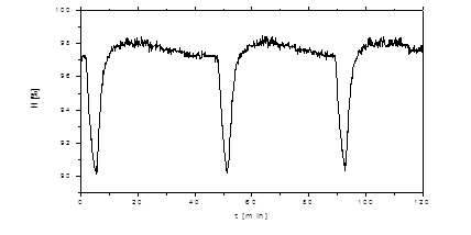
Fig. 9. Air and stored product temperature variations (upper diagram) and air humidity variations in the Chamber No. 1; temperature variations: green line – stored product; black line – air at the inlet to the air cooler; red line – air at the outlet of the air cooler.
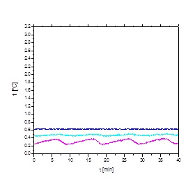
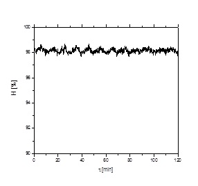
Fig. 10. Air and stored product temperature variations (upper diagram) and air humidity variations in the Chamber No. 2; temperature variations: green line – stored product; black line – air at the inlet to the air cooler; red line – air at the outlet of the air cooler.
Concerning the cooling system applied in the Chamber No. 2 the stability of the air and product temperatures, and air humidity in the chamber are presented in Fig. 10. There were small variations in air temperature at the outlet of the air cooler. During the period of low thermal loads the temperature of the exhaust air from the air cooler was very stable and close to the optimum temperature, i.e. near 0 °C. The temperature of the stored product was maintained at the stable level too and was close to the optimum temperature. Air humidity was maintained at stable high level. Because the air cooler operated continuously there process of condensation of moisture on stored product was not observed, i.e. the air cooler was always colder then the stored product. The comparison of the product mean temperature variations in the Chamber No. 1 and the Chamber No. 2 are presented in Fig. 11. Therefore it may be assessed that the cooling system applied in the Chamber No. 2 fulfils the technological requirements for the stored vegetables in terms of temperature and humidity conditions.

Fig. 11. Stored product mean temperature variations: Chamber No. 1 (black line); Chamber No. 2 (red line).
Concerning the cooling system applied in the Chamber No. 3 the stability of the air and product (Chinese cabbage) temperatures are presented in Fig. 12.
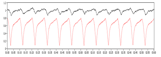
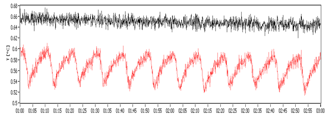
Fig. 12. Air temperature variations (upper diagram) and stored product temperature variations in the Chamber No. 3; air temperature at the cooler inlet (black line) and outlet (red line); product temperature in the centre of the chamber (black line) and next to the air cooler (red line).
The system applied in the Chamber No. 3 is characterized by a little larger fluctuations in air temperature than the cooling system applied in the Chamber No 2. As a result, there were larger variations of air temperature at the outlet of the air cooler in the Chamber No. 2 but significantly lower than in the Chamber No. 1. Similar results for the case of carrot storage were observed with use of indirect system, Grzegorzewska et al. (2013), Mizera and Butrymowicz (2011). At the present stage of the development of the design of the cooling system with the PCM accumulator achieved technological parameters were not as good as in the case of the system applied in the Chamber 2. However this may be attributed to the storage capacity of the PCM accumulator so that the modifications of the accumulator geometry is required.
- CONCLUSIONS
As a result of three studies of the cooling systems in application to the cold storage chambers of Chinese cabbage the following conclusions may be proposed:
- the best storage requirements are implemented in the Chamber No. 2 equipped with the indirect cooling system;
- the worst storage conditions were observed in the Chamber No. 1 equipped with the traditional cooling system;
- cooling system applied in the Chamber No. 3 requires further improvement along with modification of the PCM accumulator geometry;
- optimisation of fans speed may be also applied since fans speed has influence for process of drying of the stored vegetables, uniformity of the quality of the stored vegetables, as well as energy consumption.
Acknowledgement
The research presented in the paper is supported by the National Centre of Research and Development , Contract No. PBS1/A8/7/2012
- REFERENCES
Adamicki F., Czerko C., 2002, Storage of vegetables and potatoes (in Polish), Państwowe Wydawnictwo Rolnicze i Leśne, Poznań.
Gościk J., Butrymowicz D., Gagan J., 2011, CFD modelling of unsteady operation of cold storage vessel, 23rd International Congress of Refrigeration, Prague, Paper No. 680.
Kwidziński R., Mizera G., Karwacki J., Butrymowicz D., Modelling of indirect cooling systems in application to vegetables cold stores, 23rd International Congress of Refrigeration, Prague, Paper No. 695.
Mazza G., 1989, Carrots, in: Eskin N.A.M. (ed.), Quality and Preservation of Vegetables, CRC Press, pp. 75-119.
Mizera G., Butrymowicz D., Adamicki F., 2010, Stability of air temperature and humidity in context of quality of vegetables after cold storage (in Polish), Chłodnictwo, Vol. 45, No. 9, pp. 48-55.
Mizera G., Butrymowicz D., 2011, Cold store of new generation for carrot storage, 23rd International Congress of Refrigeration, Prague, Paper No. 829.
Mizera G., Butrymowicz D., Mikielewicz J., 2008, Analysis of indirect storage chamber cooling system, International Conference on Design and Operation of Environmentally Friendly Refrigeration and AC Systems, Poznań, pp. 163-170.
Gross K.C., Wang C.Y., Saltveit M. (eds.), 2002, The Commercial Storage of Fruits, Vegetables, and Florist and Nursery Stocks, Agricultural Handbook No. 66, USDA, Washington DC.
Grzegorzewska M., Badełek E., Adamicki F., 2013, Investigations of cold stored carrots under conditions of continuous and discrete cooling operation (in Polish), Conference on Modern Technologies for Horticulture with Reduction of Greenhouse Gases Emission, Skierniewice, Poland, pp. 4-8.